The front panel on the power section contains 10 rocker switches that contain colored LEDs.
The Switches & LEDs are designed for a 12 volt system, but I am using them to switch between 18 and 25 volts from a cell pack.
To keep the correct voltage for the LEDs, and to blink the LEDs in sequence, I built a circuit using TTL chips and 2 voltage regulators, so that the "Blinky Board" has a "floating ground" that is 12 volts below the battery voltage. This way, The TTL chip can pull one lead of each switch LOW, and light the LED.
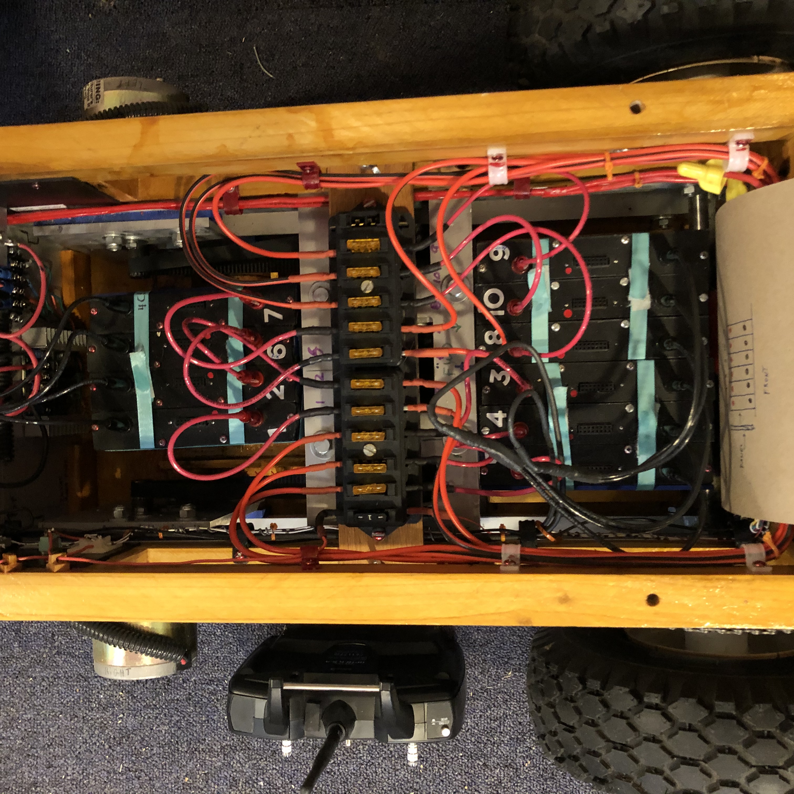
There are ten cell packs total. Each pack holds six 18650 cells, in series.
When brand new, a fully charged 18650 cell can produce 4.2 volts. Six in series can produce 25.2 volts.
When all 10 power switches are on, the packs are in parallel. (6S 10P)
Each cell pack is on it's own switch, so the voltage can be checked individually.
Also, low or defective packs can easily be isolated from the remaining packs.