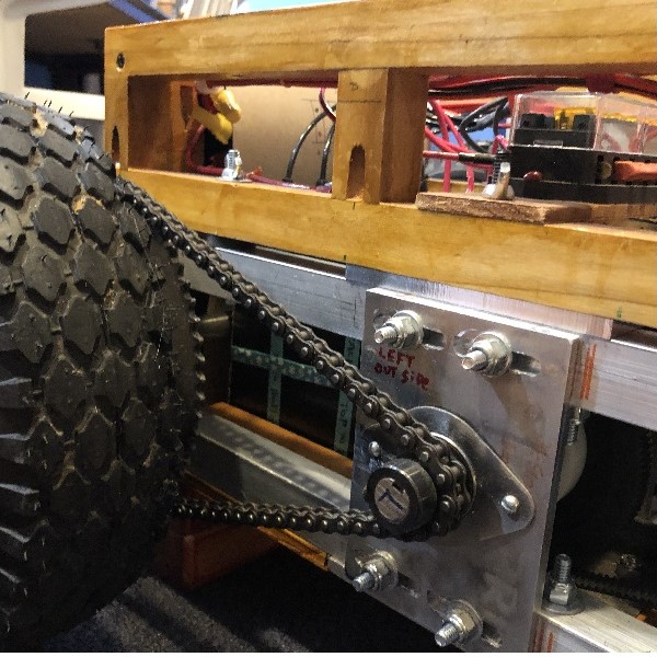
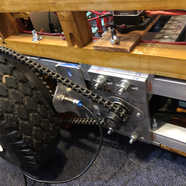
This photo shows the Chain Drive on the left side of the robot.
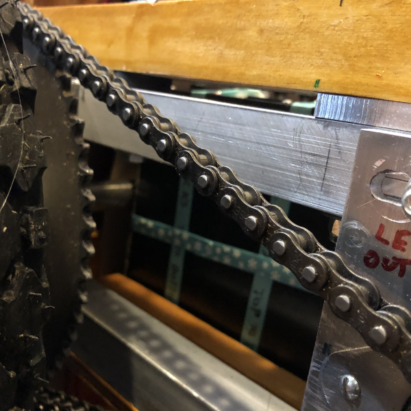
The wheel sprocket teeth are exposed just behind the wheels.
The steel sprocket teeth can be detected with a inductive proximity sensor
The diameter of the tire is 10.5 inches (267 mm)
The circumference of the tire is: Pi X Diameter or 3.14 X 10.5 = 33 inches
One wheel revolution moves the bot ABOUT 33 inches
Always assume that the wheel WILL slip on the ground.
To move the bot forward 3 feet, I need to turn on both motors until I get 66 pulses from each wheel
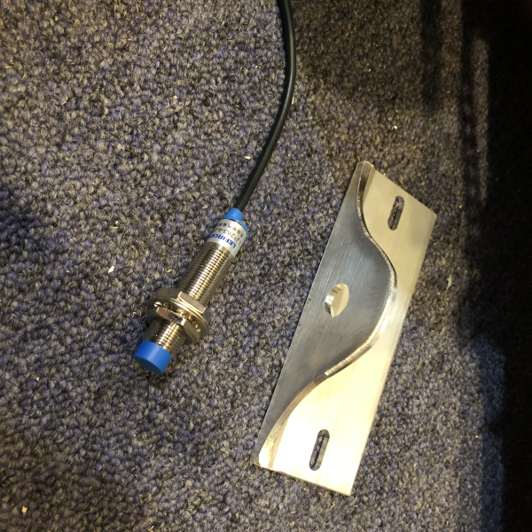
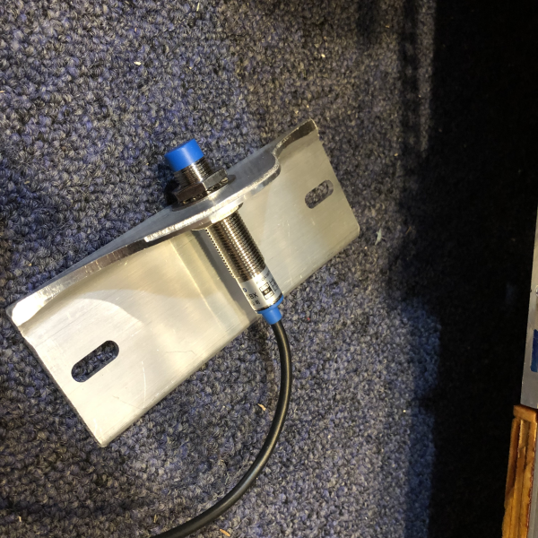
This Photo shows the Bracket and an Inductive Proximity Sensor
Inductive Proximity Sensor at MPJA.COM
MPJA.Com - - - - Stock No: 32086 HD
Part No. - - - - LJ12A3-4-Z/BX
As of 7/21/21 this part is $4.50 ( Your milage may vary)
As of 9/2021
While testing the sensors ability to detect the teeth on the wheel sprocket,
It turned out that the wheel sprocket was not spinning true enough. (Cheap Harbor Freight Wheels)
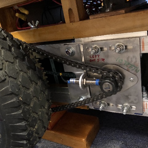
When turning, the sprocket wobbles so much, that the sensor only picks up SOME of the teeth. This was happening on BOTH wheels. I was able to do some adjustments, but I also moved the sensor to point at the DRIVE sprocket, on the jackshaft. The smaller sprocket spins much truer.
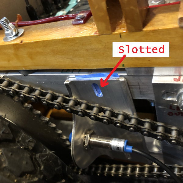
The bracket can be adjusted up and down, using the slots.
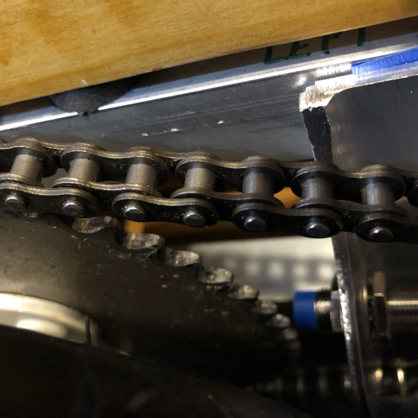
The bracket can be moved in and out using shims behind the brackets
The sensor is threaded, which allows the sensor to be adjusted toward the sprocket.
My plan is to have sensors on both of the wheels. The sensors will be connected to
an Arduino that will count the pulses, and send two 16 bit integers to the COM port.
The COM port can be read by a program running on the PC inside the bot.
The PC can get a reading from the Arduino before it starts the motors, and another reading
when it stops the motors. A simple subtraction of the readings can tell me how far the bot has traveled.
It turned out that the wheel sprocket was not spinning true enough. (Cheap Harbor Freight Wheels)
When turning, the sprocket wobbles so much, that the sensor only picks up SOME of the teeth. This was happening on BOTH wheels. I was able to do some adjustments, but I also moved the sensor to point at the DRIVE sprocket, on the jackshaft. The smaller sprocket spins much truer.
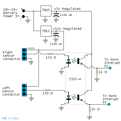
the Arduino Nano requires 5 volts. In addition, the sensor signal is 12 volts, but the Nano needs 5 volt logic inputs.
I drew up a diagram that looks like this :
This circuit provides the regulated voltages and uses an opto-isolator to level-shift the sensor signals.
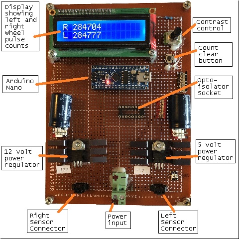
When this photo was taken, I hadn't wired in the opto-isolator.
The Odometry board is now mounted in the rear of the control panel section. It is connected to the main power bus, and the two magnetic proximetry sensors. A USB cable runs from the Arduino, to a USB hub connected to the VOOM computer.
Code in the Arduino writes the pulse counts from the two sensors and a calculated "speed" for the left and right wheels, to the USB port.
Software in the VOOM computer reads these values, where they can be used for navigation.