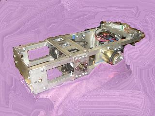
For my second version, I used STEEL tubing. This was very heavy, so I made the frames again, but I used aluminum.
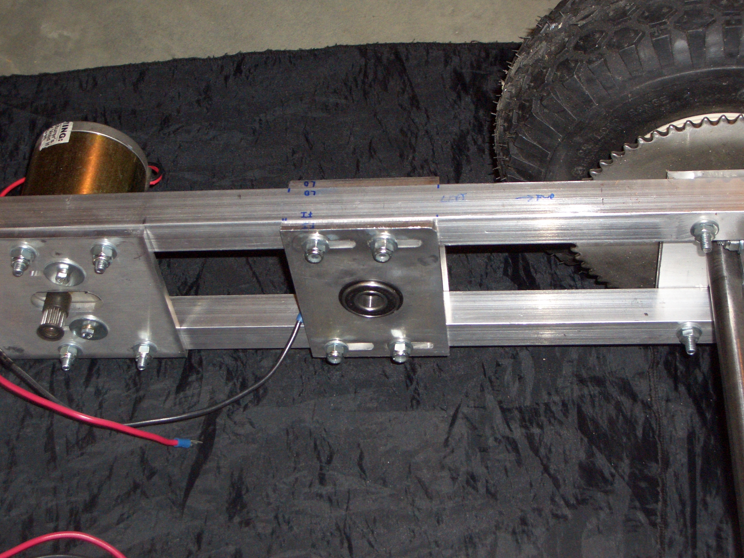
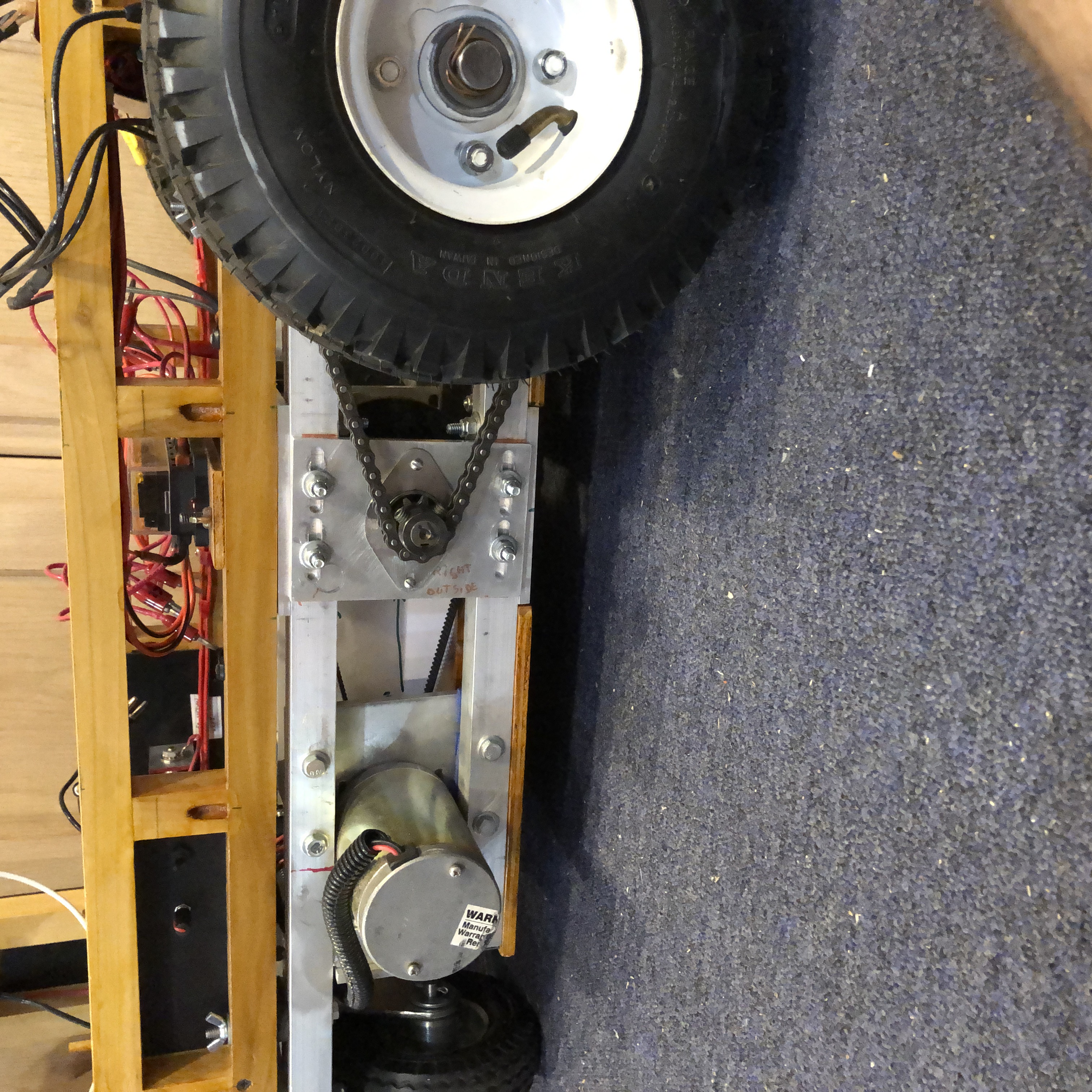
Later photos show the new bearing support design.
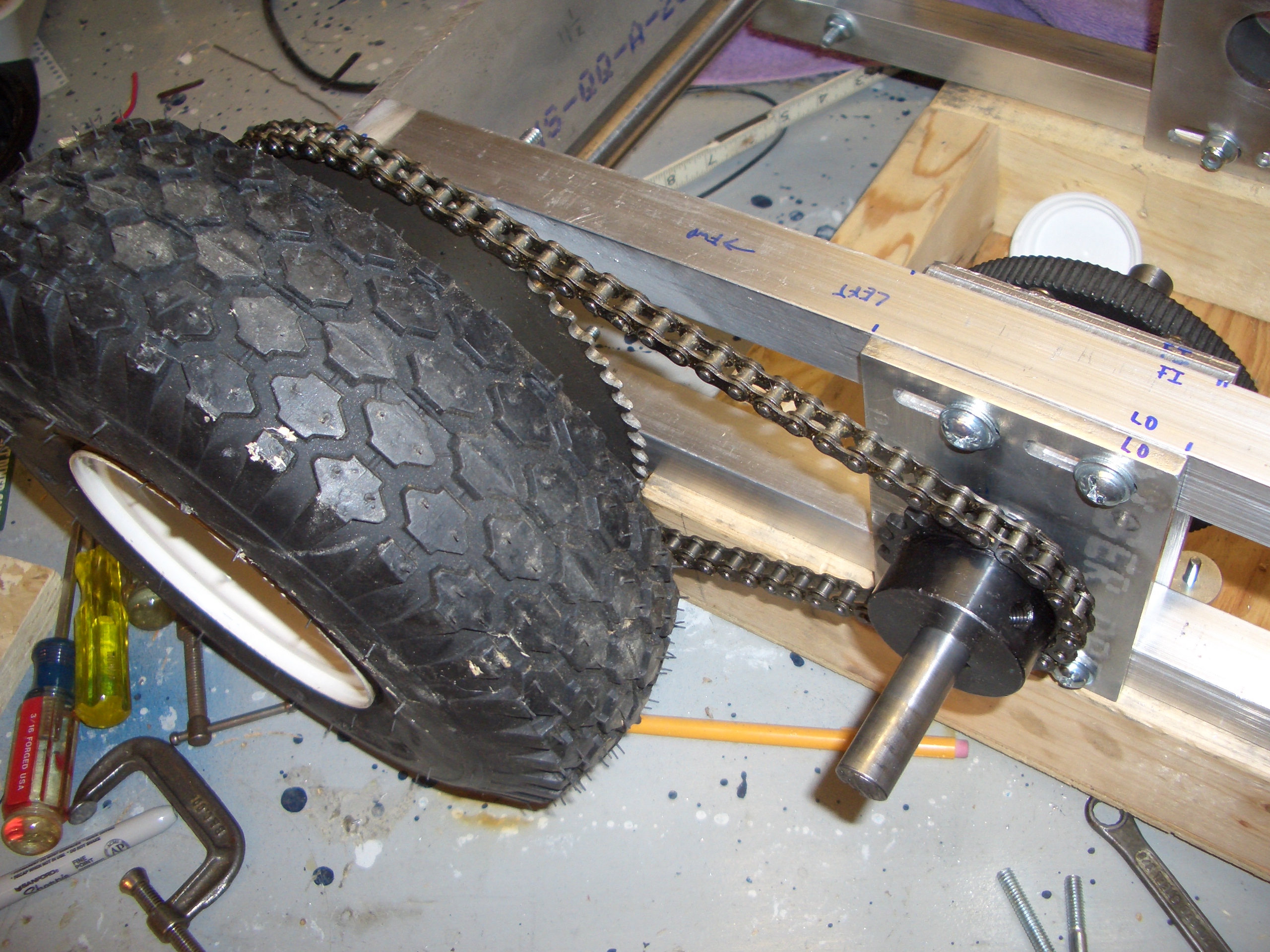
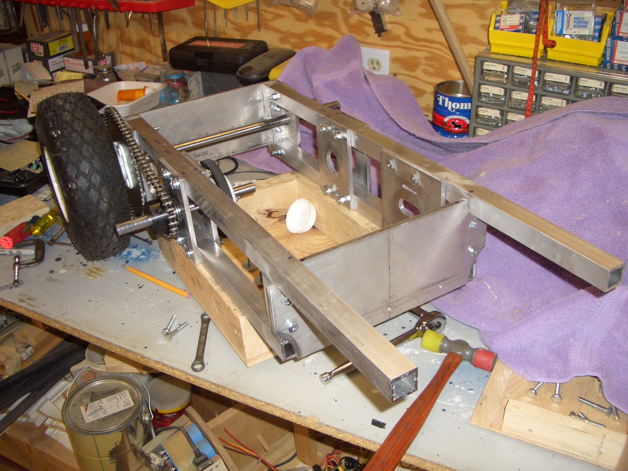
On the inside of the frame, the toothed pulley is visible on the jackshaft.
This pulley was removed from the canibalized scooter, along with it's Motor and belt.
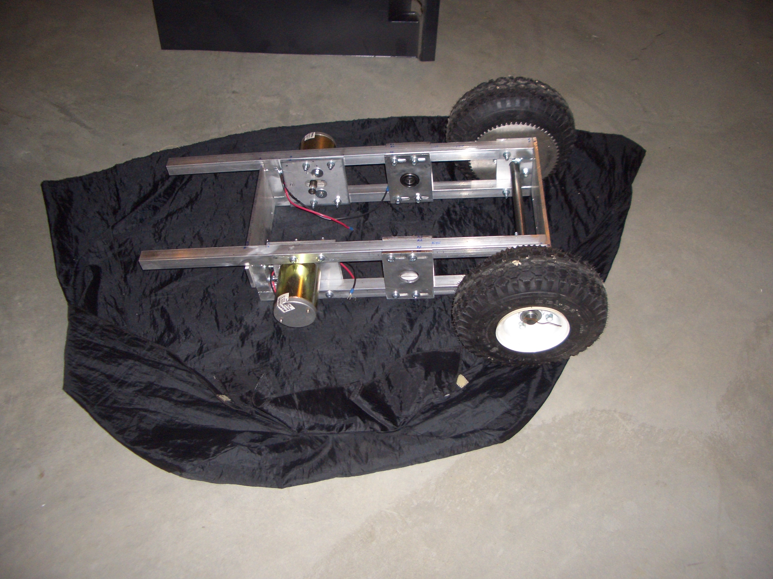
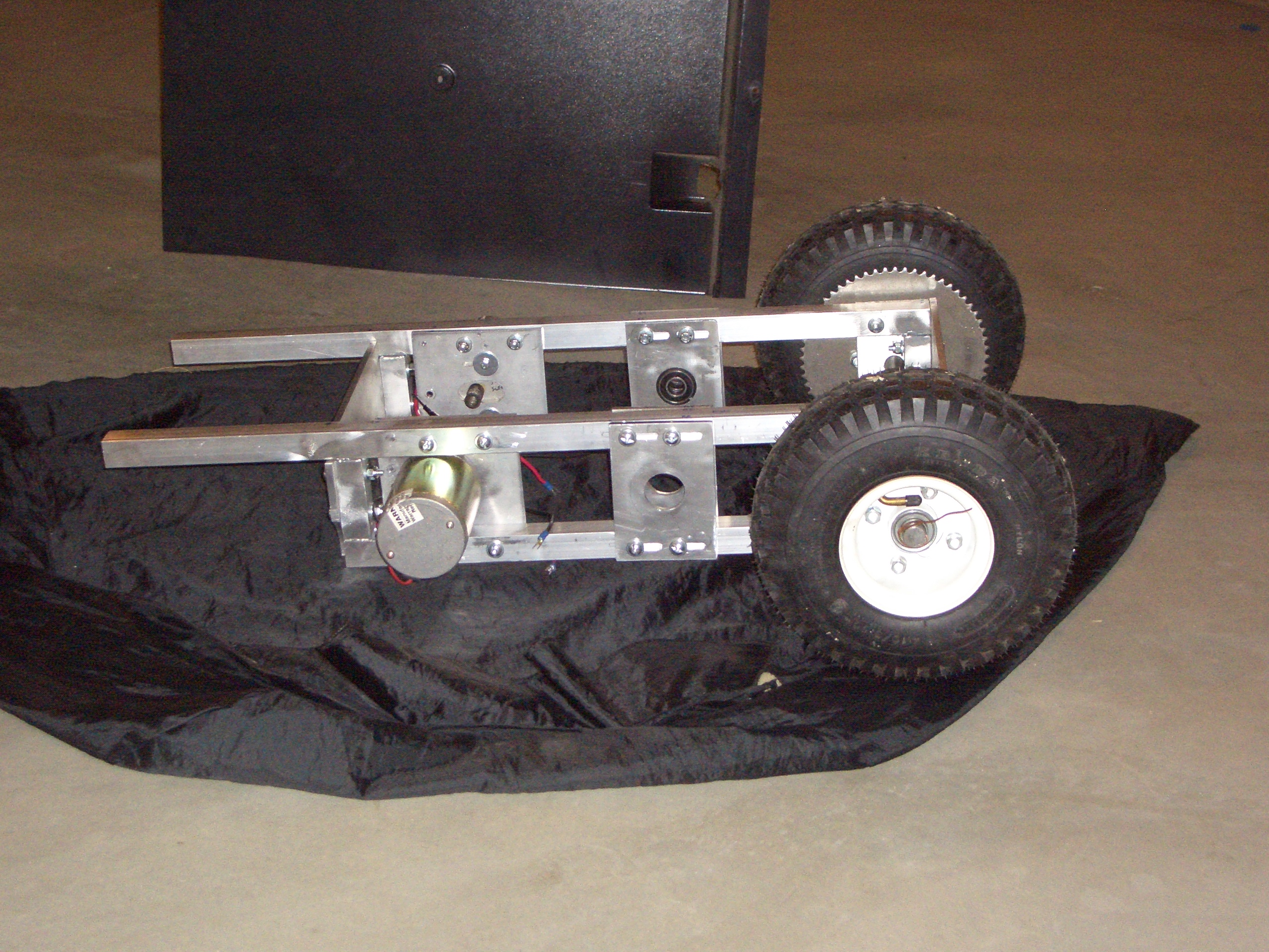
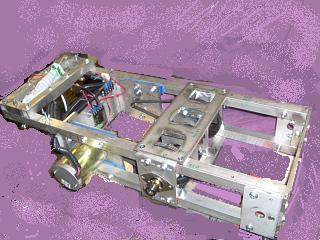
The height of the frame was determined by the size of the caster and the size of the two driven wheels.
The height was chosen to make the frame level when all three wheels are mounted.
All three wheels were purchased at a local "Harbor Freight" store.
I chose to go with a single caster - 3 wheels instead of 4. Early test machines showed that 2 casters could become "high centered" on uneven terrain. With 2 casters, it was possible that one of the drive wheels could be held above the ground, and the robot could not steer out of the hole without spinning.
With 3 wheels, they are always on the ground.
The bearings are further apart, and there is one bearing on each side of the toothed pulley, so the shaft stays straight when the belt is under tension.
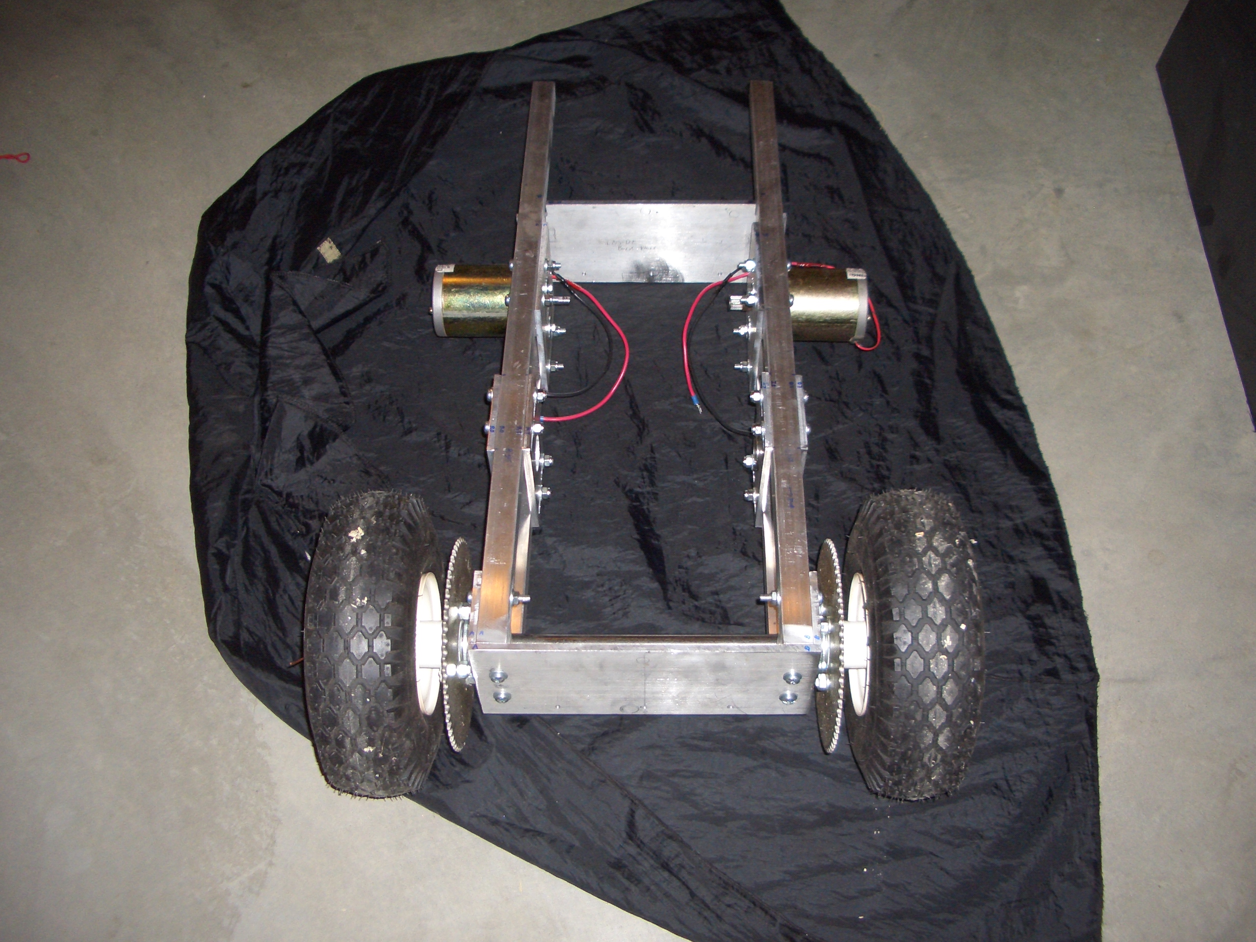
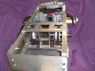
Two 1/4 inch aluminum plates had to be made, mounted on the top and bottom of the square tubing. This meant modifying the bottom panel, and it meant raiseing the power section up 1/4 inch.
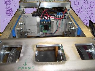
The rear plate doubles as a heatsink for the "Sabertooth" motor driver.
The top and bottom jackshaft plates each contain 3 rectangular holes. These holes are not only for weight reduction, but these are necessary for access to the nuts and bolts that hold the bearing plates.
The bearing plates are slotted and access to the fasteners allows for the adjustment of the belt and chain tension.
The jackshaft bearing plates are slotted to allow adjustment of the belt and chain tension.
The motor mounting plate is also slotted for the same reason.
The bearings are held in place by steel "Bearing Keepers" that I cut from a deceased PC power supply case.
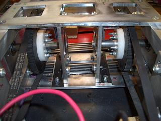
The toothed pulleys and belts came from a "Silver Bomber" scooter.
The white pieces, screwed onto the toothed pulleys, are made from acrylic. These were necessary because the hole in the pulley is a larger diameter than the jackshaft. The jackshafts contain "Keyway slots" and so do the white acrylic adapters, and the small sprocket on the shaft.